Table of Contents
01ExploringSolarCells
Overview
Basic electricity concepts (voltage, current etc) are reviewed. Review of how to use a multimeter. Students experiment with solar cells and discover their properties, then learn about how photovoltaics work.
Materials
- Solar Cells - 1/every 2 students (plus a few extra for if they're broken)
- Multimeters - preferably 1/every 2 students
- Small-valued resistors - 1/every 2 students (plus a few extra if they're lost) The smaller the better; 1 ohm is good. If you only have larger, you can to put several in parallel.
- Small Pieces of cardboard - about solar cell sized, useful for carrying cells without breaking them
Background Concepts
This section provides explanations and analogies which may be useful in understanding and explaining key concepts during the course of the lesson. Once the teacher has a good understanding of the concepts, she/he can guide the rest of the students to understanding through the series of hands-on experiments and projects outlined in the next section.
Solar Energy
Solar energy, or energy from the sun, reaches the Earth as radiant heat and light. This is apparent from everyday experience; you can feel and see the heat and light from the sun during the day. It is possible to capture and use solar energy in both its forms. For instance, if you leave water out in the sun, it heats up over the course of the day, capturing heat energy. This same concept is used in solar ovens, which capture solar heat in closed ovens to cook food. We can also capture the energy stored in the sun’s light. For instance, the energy in UV light can be used to purify water. In this lesson, however, we will use solar panels to capture the energy stored in light and convert it to electrical energy. Electrical energy can then be used to recharge a battery or power a circuit.
Light
So how does light store energy? Just as matter is made up of smaller particles like atoms, light can be thought of as being made up of lots of little particles called photons. Each photon has a certain amount of energy. The amount of energy carried by a particular photon depends on the color of the light. For instance, the photons that make up low-frequency red light have less energy than those that make up high-frequency blue light. Light from the sun, which contains all frequencies of light, contains photons of many different energies. Consider the photons to be balls, with the amount of energy carried by each dependent on the size of ball. Low-energy red light would be like a stream of small tennis balls, while high-energy blue light would be like a stream of big footballs. When both streams come at you at the same speed, the stream of footballs will carry more energy. When light from the sun falls on the solar panel, it’s like a stream of “photon-balls” of many different sizes hitting the solar cell.

Solar Cells
What happens when the photons hit a solar cell? In short, the energy from the photons is transferred to electrons in the cell, freeing the electrons from their atoms and allowing them to move around in the material. The design of the solar cell forces electrons to flow in a single direction, creating a current which is captured as electrical energy.
To better understand how this works, one must understand the structure of a solar cell. A solar cell is made up of a type of material called a semiconductor. Unlike a conductor, semiconductors don’t contain free electrons to carry a current easily. However, the electrons in the semiconductor aren’t held onto very tightly by the atoms. So although they can’t move around, when hit with a photon with enough energy they will break free of the atoms and behave like they would in a conductor. The following diagram illustrates the ball analogy; when a ball with sufficient energy hits the cell, it can cause the electrons to break free of the material and move freely.

Once the electrons are free, they can move around randomly. In order to get a current, however, the electrons must only flow in one direction. What would make this possible? In a solar cell, there is an electric field across the cell. A solar cell is made up of two slightly different layers of semiconductor, which result in a positive and negative side to the cell. This electric field exerts a force on electrons and only allows them to flow in one direction, and thus the cell produces an electric current.

This electric field represents the voltage of the solar cell - the front and back of the solar cell are like the positive and negative terminals of a battery. The amount of light that hits the solar cell doesn't affect the voltage - more light will just increase the current produced by the cell. This is why if you cut a cell into pieces, each of the pieces will have the same voltage as the original cell, but far less current. The electric field from the front to the back of the solar cell is unchanged, but since each of the pieces has less area than the original cell, they collect less light and so produce less current.
What can you expect to happen in blue light versus red light? What about more light versus less light? In the first instance, since blue light has higher energy photons than red light, one could expect that blue light would free more electrons and produce higher currents than red light. Likewise, more light means a greater quantity of photons, so one could again expect more light to free more electrons and produce higher currents.
The power produced by solar panels is also greatly affected by their angle in relation to the sun. If they are angled so that the sun shines on them directly, a lot more photons will be hitting the panel directly, freeing more electrons and creating a larger current. However, if the sun shines on the panel at an angle, less electrons will be freed.

Solar Cell Power
The amount of light hitting a solar panel does not affect its voltage. Once a cell or panel has an electrical load on it (for example, a resistor), however, the voltage will change. Again, this should be discovered experimentally, but the voltage a cell produces when a small resistor is added to the circuit will be lower than when just connected to the multimeter.
Why is this? Without a connected circuit, or with a very high resistance load (remember - a gap in a circuit is similar to “infinite” resistance) the voltage produced by the cell is called the Open Circuit Voltage. (Remember that Voltage = Current x Resistance); if the cell produces a low current, but the load has a very high resistance, the voltage produced will also be high.) The multimeter has very high resistance, so when we connect it directly to the panel we are essentially adding a huge load to the panel, and the cells can maintain a high voltage without much current.
On the other hand, if the load is a small resistor, much more current would be required to produce the same voltage. Since the cell cannot produce enough current, the voltage decreases.
Every solar cell has a characteristic “IV Curve” that relates the current produced by the cell to the voltage across it for a specific amount of light. At one extreme is the open circuit voltage, as described above, with very low current and very high voltage. At the other extreme is the short circuit current, which is the maximum current produced by the cell when voltage across it is zero. Changing the load across a cell will cause the current and voltage produced by the cell to change, changing the point along this curve at which the cell is operating. Since the power produced by the cell is the product of current and voltage, this graph provides a good visualization for the amount of power produced by the cell at each operating point along the curve:
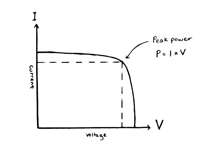
From this, one can see that the power produced by the cell changes depending on the load, even though the amount of light hitting the cell is the same throughout. Decreasing the load across the cell will move the operating point towards the short circuit current, while increasing the load will move it towards the open circuit voltage (as measured with the voltmeter).
Why is this? As the load across the cell is decreased, the current required to maintain the open circuit voltage increases. The voltage produced remains relatively constant at first, until the cell can no longer produce enough current to maintain the voltage, and the voltage drops off rapidly. This occurs at the short circuit current of the cell, which is the maximum current it can produce. Note that the power produced by the cell is at its maximum at the point just before the voltage drops off. This point is called the Maximum Power Point (MPP) of the cell, and the cell will produce the most power when operating at this point.
Solar Cell Efficiency
Solar cells cannot convert light energy completely into electricity. The light from the sun produces roughly 1000 Watts per square meter of energy at the surface of the Earth, but this is not all converted into electricity. Only certain energies of light have enough energy to free electrons from the material in the cell, and other energy is lost as heat or light that is reflected rather than absorbed by the cell. For this reason, the cell is not 100 percent efficient. The efficiency of a solar cell is usually described as the ratio of power produced by the cell at its Maximum Power Point to the power it would produce if it completely converted solar energy to electricity. For instance, a panel with an area of 1 meter squared that produces 100W of power at its maximum power point is 10% efficient, based on the approximate solar energy incident at the Earth’s surface.
Lesson Plan
1. GO OVER BACKGROUND
Do students have a solid understanding of electricity? If not, this is a good place to either teach or review the concepts behind electricity at the electron level. See “Current, Voltage & Circuits” in the background information section of the main lesson book for reference. Water or other analogies may be helpful here. Make sure students have a solid understanding of the meaning behind voltage and current, and can apply them at a conceptual level. Ask questions to ensure that students understand the concepts and have not merely memorized definitions. Review both current and voltage as needed, using waterfalls or other useful analogies.
2. MEASUREMENT TECHNIQUES
After reviewing current and voltage, demonstrate the use of a multimeter for measurement. The measurement for voltage is relatively simple; students should understand how to turn the knob to the correct measurement, connect the leads, and how to factor in order of magnitude of the multimeter measurement. If the multimeters don’t have good current measurement (as in most cheap multimeters), current should be measured by finding the voltage drop across a resistor and using Ohm’s law (Voltage = Current x Resistance, or V = IR). Ohm’s law may also need explanation and review.
3. MEASURING SOLAR CELLS
Before letting the students use the solar cells, it is important to review proper handling of the cells, and mention how delicate they are. As a demonstration, break a solar cell in front of the class! This is engaging, a good demonstration, and will also give you the small pieces of cell necessary for the measurement exercise.
To measure the solar cells, bring the students outside with solar cells, cell pieces, multimeters, and resistors. Having the students work in pairs is optimal, even if materials allow for students to work individually.
Together, students should measure the voltage and current produced by a full cell, finding the maximum by tilting towards and away from the sun. Students should next find the maximum voltage and current of a partial cell, and compare the results.
Students should write down the voltage results they got in notebooks and keep the results to use in the next lesson, where they will design solar panels using full and partial cells.


4. DISCUSSION
Students should find that the voltage is the same between a full cell and a piece of a cell. The current produced by the smaller piece should be less.
Once students have discussed their results, the teacher can begin introducing the physics behind solar cells. This discussion can be adapted based on student understanding, and may be slightly more in-depth if students have a working knowledge of valence shells, atomic bonding, and so on. This may be a good place to connect the lesson to other classroom learning, or to introduce bonding and other topics that may not have been taught previously. Having visual aids like blackboard drawings or other visualizations may help student understanding.
By the end of the discussion, students should understand some level of the physics behind solar cells: the incidence of light of specific frequencies on the cell, collisions between photons and electrons to excite them, how semiconductors behave, and the structure of the cell (layers of doped silicon, electric field across the cell – like a diode, etc.) to produce current. It may also be interesting to connect this lesson briefly to the structure of diodes and transistors.
Once students understand photovoltaics to some degree, they should be able to understand the results of their outdoor experimentation. The voltage is the same in the full and partial cells, because the structure of the cell creates a constant voltage drop between the front and back of the cell, despite its area. Current, however, is smaller in the piece because fewer electrons are being hit and freed.
5. WRAP-UP
- What could you use solar power for?
- what would be the challenges and how might you overcome them.
- next lesson will be learning how to get more from cells and panel design.