Table of Contents
<a href="?do=export_pdf">Printable PDF</a>
06LampCircuitDesign
Overview
In this lesson the club reviews basic circuit concepts, then learns about the circuits required to create a battery-charging solar lamp (how to prevent overcharging and overnight discharging). They then design and test their own circuits using simple components.
Materials
- Solar panel + battery from lesson 5
- an assortment of electrical components (diodes, LED's , resistors, switches) could be helpful to show the class
- Pen/pencil and paper
- Place to draw in front of class (blackboard, overhead projector etc)
Background Concepts
1. Battery overcharging
We know that batteries are used to supply power to a circuit. They use an electrochemical reaction to make electrons flow between the two battery terminals, turning chemical energy into electrical energy. Rechargeable batteries work the same way, but the reaction can be reversed – applying electrical energy to the battery reverses the reaction, turning it back into chemical energy within the battery. The battery can then be used to power a circuit again, and then recharged again when it runs out of energy.
The most common type of rechargeable battery is a lithium ion battery – these are the batteries found in mobile phones (which we all know are rechargeable!).
For this lesson: have the club bring in mobile phone/camera batteries to charge. They must NOT be fully charged (see below).
WARNING: If lithium ion batteries are over-charged, they can overheat and cause a fire, or damage the battery. Since we won't build a circuit to stop this overcharging from happening until the second part of the lesson, you should be careful to start the lesson with partially charged batteries. To make sure they are only partially charged, measure with a multimeter (a fully-charged battery is around 4.5V - the batteries should be less than that) or use one from a mobile phone that has been used for several hours, but can still turn on.

2. Reading circuit diagrams
Circuits are essentially a power source and components connected by wires – the circuit has to be 'complete' (i.e. connected in a full circle) otherwise current will not flow. Circuit diagrams are basically precise ways of representing a circuit, with different symbols for each component. Components that are electrically connected (through wires, or by directly connecting them together) are connected by simple straight lines. Components would be difficult to draw realistically, so they are represented by symbols. A few common circuit symbols (you can draw these on the board):
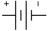
Battery/other voltage source: Note the positive and negative terminals.
Resistor: Shown below is what a standard resistor looks like in real life. The squiggly line is the US standard resistor, the box is standard in the UK and some other commonwealth countries (e.g. Ghana).

Diode: Components that let current go through in one direction but not the other. The direction of the arrow indicates the direction current can flow. The diode direction is usually indicated by a marking as shown below.

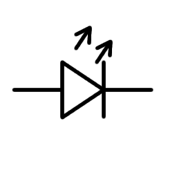
Light-emitting diode (LED): Operates in the same way as a diode (one-directional) but also emits light.

Switch

On below is a picture of the simple panel circuit: a voltage source (the panel) is connected in series with a battery and a resistor.

Below is a simple overcharge circuit – note how the LED and switch are connected in series, but are both connected in parallel with the battery. Make sure the students understand how series and parallel connections are represented – maybe even show some real-life examples.

3. Charging/Discharging
When a solar panel properly connected to a battery is put in the sun, the panel will generate a current which will flow in the circuit, charging the battery. If a battery is connected to a solar panel that is in darkness, the panel will not generate current. But because there is still a complete circuit loop, and a voltage across the battery, current will still flow in the circuit, but this time it will flow in the opposite direction and discharge the battery.


For a solar lamp, we want a circuit that can charge when the solar panel is in the sun, but we want to stop it from discharging when the panel is in the shade. To do this, we can find a way to only let the current flow in one direction – the direction that charges the battery.
4. Diodes
A diode is a component that only lets current flow through it in one direction. A diode and its circuit symbol are shown below:
A diode lets current pass through it in one direction, but if the current is flowing in the other direction, it cannot get past the diode.

If we add a diode to the charging circuit such that it allows current to pass only in the direction that charges the battery, the battery won’t drain even when the solar panel is unlit.


In this lesson: How to teach about diodes
After seeing the results of the discharging experiment (the panel-battery circuits the class left overnight in the last lesson), the group should have come to the conclusion that when the solar panel is in the sun, current flows one way and charges the battery, but when in shade it flows the other way and instead discharges it.
Ask the group for ideas about how they might prevent this from happening. Don't tell them to use a diode right away! Try to get someone to suggest it, or at least suggest that we need something that will only let current flow in one direction. After that, introduce diodes as a device that can do this.
Remember that LEDs are diodes. Students might remember that LEDs only light if they are connected up the right way – this is because they only let current flow in one direction. Let the club play with LEDs so see this for themselves if they want.
5. Overcharging circuit
As previously mentioned, it can be very dangerous to overcharge a battery. We need to introduce something into the circuit that stops the battery from charging once it reaches a certain voltage. For a lithium ion battery, it is fully-charged when there is a voltage of 4.5V across the terminals of the battery.

Another property of diodes is that they only let current flow through them if the voltage across them is higher than a certain amount. They are like switches that turn on once a high enough voltage is applied.

This property can be used to prevent overcharging in a battery.
The voltage that the diode has to reach in order to conduct current is called the 'turn-on voltage'. Before the turn-on voltage is reached, the diode behaves like it is an open circuit – no current is flowing.
Once the turn-on voltage is reached, it behaves like a short circuit – it has very low resistance - and (in a simple model) will always have the turn-on voltage across it for any amount of current.
This means that: If a diode is in parallel with another circuit component and the voltage across them is under the turn-on voltage of the diode, then almost all the current will go through the other component.
If the voltage is above the turn-on voltage, almost all the current will go through the diode.

Different diodes, such as different colors of LEDs, will have different turn-on voltages. If we put several diodes in series, they will behave as if they are a diode whose turn-on voltage is the sum of the turn-on voltages of each individual diode. This is because each diode needs its individual turn-on voltage across it to conduct, and because they are in series, the voltages add and they must all conduct for any one to conduct.

Therefore a string of diodes (such as LEDs) can be used to divert the current away from a sensitive component (such as a Li battery) when the voltage reaches a threshold (such as the 4.5V for fully charged). When the voltage is below 4.5V, the diodes won’t let current through, and the current will instead go through the battery and charge it. Once the voltage across the battery reaches 4.5V, for fully charged battery, the string of LEDs begins to allow current through, and current no longer passes through the battery, preventing it from overcharging.
6. Building the rest of the circuit!
Example circuit 1: This is the most obvious circuit – the battery is connected in parallel with both the LED string (acting as the overcharge diode) and the lamp – LEDs, a switch and a resistor connected in series. It is also connected in series with the diode (or normal LED) we used to stop power leaking when the solar panel is not in light in the first experiment
Example circuit 2: This is slightly less obvious – it combines the lamp with the overcharge circuit. When the switch is closed, the LED string acts as the lamp. When it is opened, it combines with an extra LED (potentially a coloured LED) to provide the 4.5V needed for overcharge protection. The coloured LED is not included in the lamp, so that only white light is emitted.

Lesson Plan
1. RESULTS OF DISCHARGING EXPERIMENT
Have the club take out their solar panels-battery circuits (that were left to discharge since the last lesson) and measure the voltage across the battery terminals. They should find it to be significantly lower than it was last time!
2. INTRODUCTION OF DIODES
Ask how we can prevent the battery from draining when the solar panel is not connected? Ask for ideas! Don't tell the club about diodes straight away! Try to get someone to suggest diodes, or at least “something that lets current go one way, but not another”. If someone gets this remind them about LEDs – they only work if you connect them one way – this is because they only let current flow through them in one direction – they are diodes! You can use an LED in your circuit to only let the current flow one way.
Have the group draw on a board/paper what the circuit will look like with a diode in it.
Everyone should add a diode/LED to their circuit, and use the multimeter to confirm that it does allow the battery to charge in the sun but not discharge in the shade.
3. OVERCHARGE PREVENTION
Depending on the experience the class has had with circuits, you could introduce this in one of two ways.
1. Remind the students that the batteries will catch fire if overcharged (note: their mobile phone chargers have a circuit built in that stops them from overcharging the batteries - it could be good to reference this to show that the class is building a circuit that's used in real life!). Brainstorm about how you might stop the battery from overcharging, then introduce the property of diode “turn-on” voltage.
2. Ask about other properties of diodes, and how they would be useful in a charging circuit.
4. READING CIRCUIT DIAGRAMS
Introduce the concept of circuit diagrams – a way of clearly drawing things that are electrically connected. Show some common symbols or draw them on a board (leave them up somewhere students can see them?) and explain how the lines represent electrical connections. Show some “real life” examples (e.g. make a simple circuit and draw it, or draw their solar panel circuits)
5. COMPONENTS
Briefly go over diodes again, discuss the properties of other componets – resistors, LEDs, switches.
6. CIRCUIT DESIGN
From discussing diodes, the club should have a good idea of circuits that can charge the battery when we need to use it in the sun, and prevent it from overcharging. Now you want to design something that uses it to light a light when it discharges!
Discuss with the club how they might do this – where they would connect the lamp? Where would they connect the switch? Since our overcharge circuit is made of LEDs, could we combine the overcharge circuit with the lamp?
Have the club draw some circuits that could work. Let them have access to circuit components and wires so they can play around with them if they want to. If needed, refer to the examples given in the background info to help students come up with ideas. Try to ask them questions that will lead to one of these circuits instead of giving it to them outright. At the end of the lesson, everyone should have drawn a circuit that they will solder together in the next lesson.